
Circuit Tester
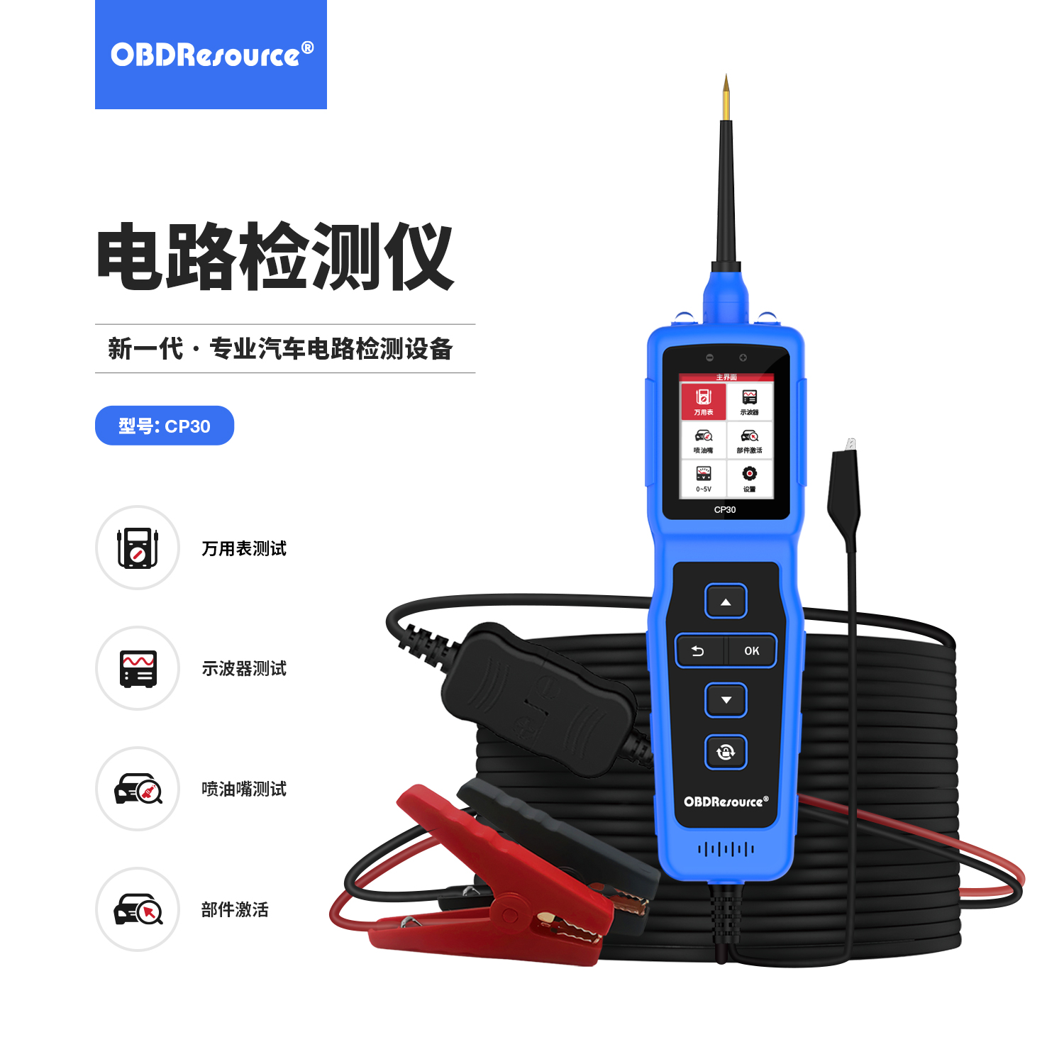
CP302.4-inch Circuit Tester with Waveform & Injector Pulsing
2.4-inch circuit tester with voltage/waveform checks, compatible injector pulsing and component activation. 8–32 V input, 0–80 V DC testing; matching A02 version adds 0–5 V simulation.
Product overview
The CP30 combines voltage measurement, polarity/ground checks, continuity and component activation in a handheld probe for use with vehicle wiring diagrams. Measurement and active power application are different operations: identify the circuit and component limits before selecting a function. Check supply, measurement range and output-current limits separately.
Key capabilities
Voltage, polarity and wiring checks
Check DC voltage and polarity, then use the auxiliary ground lead for continuity/ground checks and to help locate trailer-light, connector and short-circuit issues. Isolate circuits for continuity as instructed; continuity alone does not prove correct behavior under load.
Activate within rated conditions
Apply positive supply or ground to permitted components as instructed, up to 8 A. The 0–80 V measurement range is not an activation-output voltage rating; output depends on the connected supply and circuit conditions.
Working reach and protection
Long leads and extension options aid access, with lighting and overload protection. Investigate shorts, load or wiring after a trip before resuming as instructed.
Injector pulsing and component activation
Compatible off-vehicle injectors can use four preset pulses or custom frequency/pulse width. A02 adds current-limit and activation options. Match cables, component ratings and professional test conditions; this is not automatic cleaning, flow metering or universal high-pressure-injector support.
Waveform viewing and low-voltage simulation
View suitable camshaft, crankshaft, injector and EGR signals plus CAN polarity. A02 0–5 V simulation is limited below 100 mA and differs from 8 A activation; use the correct mode and vehicle procedure.
Suggested workflow
Identify the circuit and tool limits — Check the wiring diagram, component rating, supply range and intended test; inspect leads and perform the prescribed self-test.
Measure before deciding on activation — Check voltage, polarity and connections first. Activate only components approved for external power and do not energize unidentified circuits.
Record and verify — Interpret readings and load behavior with the diagram, investigate abnormalities and restore/check connections after testing.
Frequently asked questions
Why do input, measurement and activation limits differ?
Input powers the tool, the measurement range specifies readable voltage, and activation limits govern output/load. They are not interchangeable; measurement limits do not define output voltage.
Can the activation switch be used on any terminal?
No. Verify terminal function, isolation and allowable voltage/current using service information. Activate only suitable components and do not activate during continuity tests.
Does overload protection prevent all damage from misuse?
No. Incorrect voltage, terminal selection or sensitive circuits may still be damaged. Protection assists correct operation; wiring and rated limits remain essential.
Product design
Documentation and support
Key features
Applications
Technical specifications
| Item | Specification or function |
|---|---|
| Model | CP30 |
| Input supply | 8–32 V |
| DC test voltage | 0–80 V |
| Operating current | <90 mA |
| Activation current limit | 8 A |
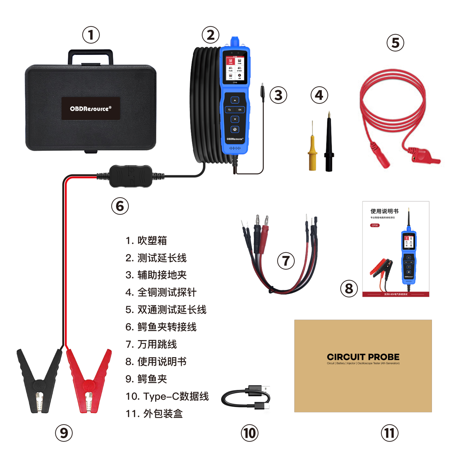
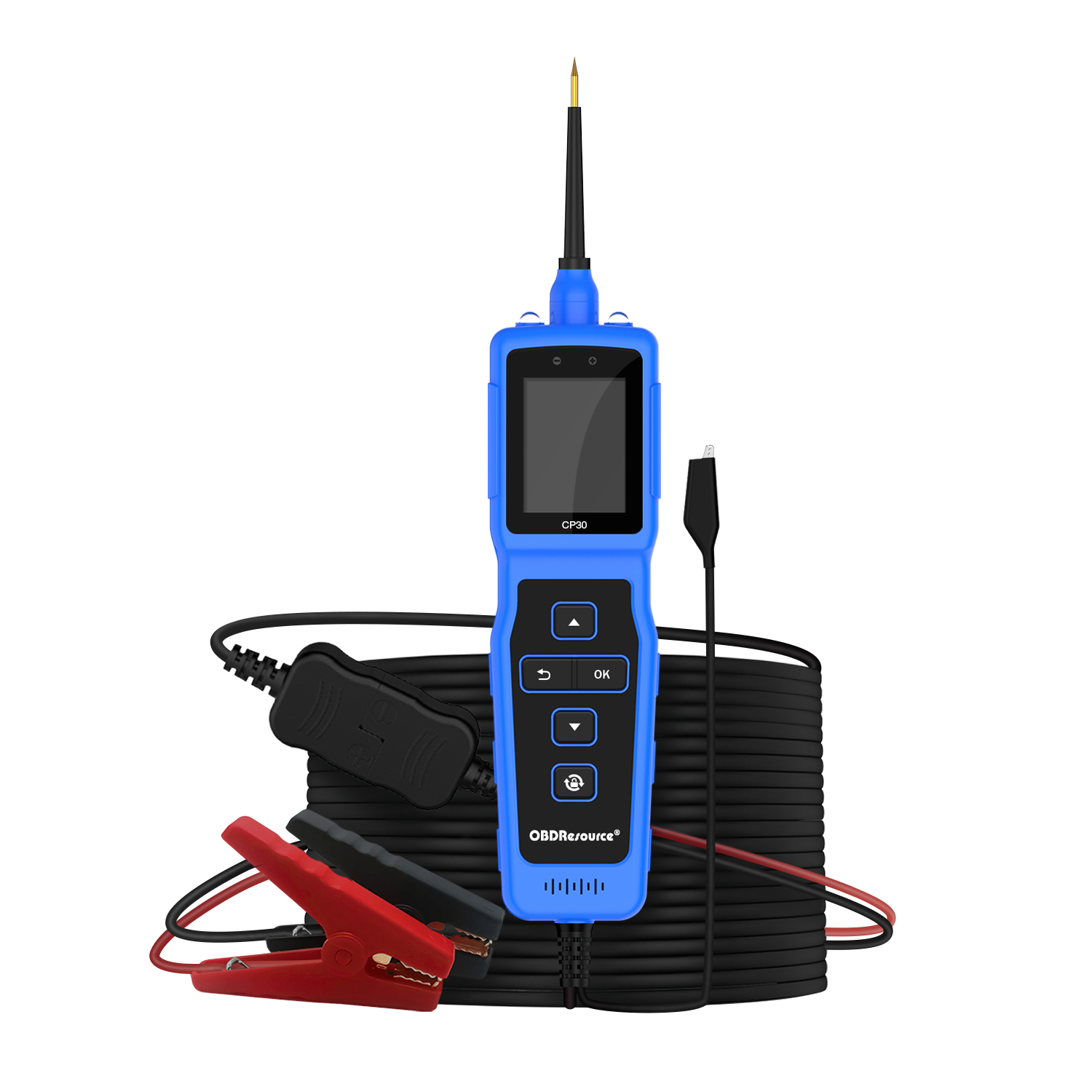
| Cable configuration | Extension lead included; verify supplied lengths |
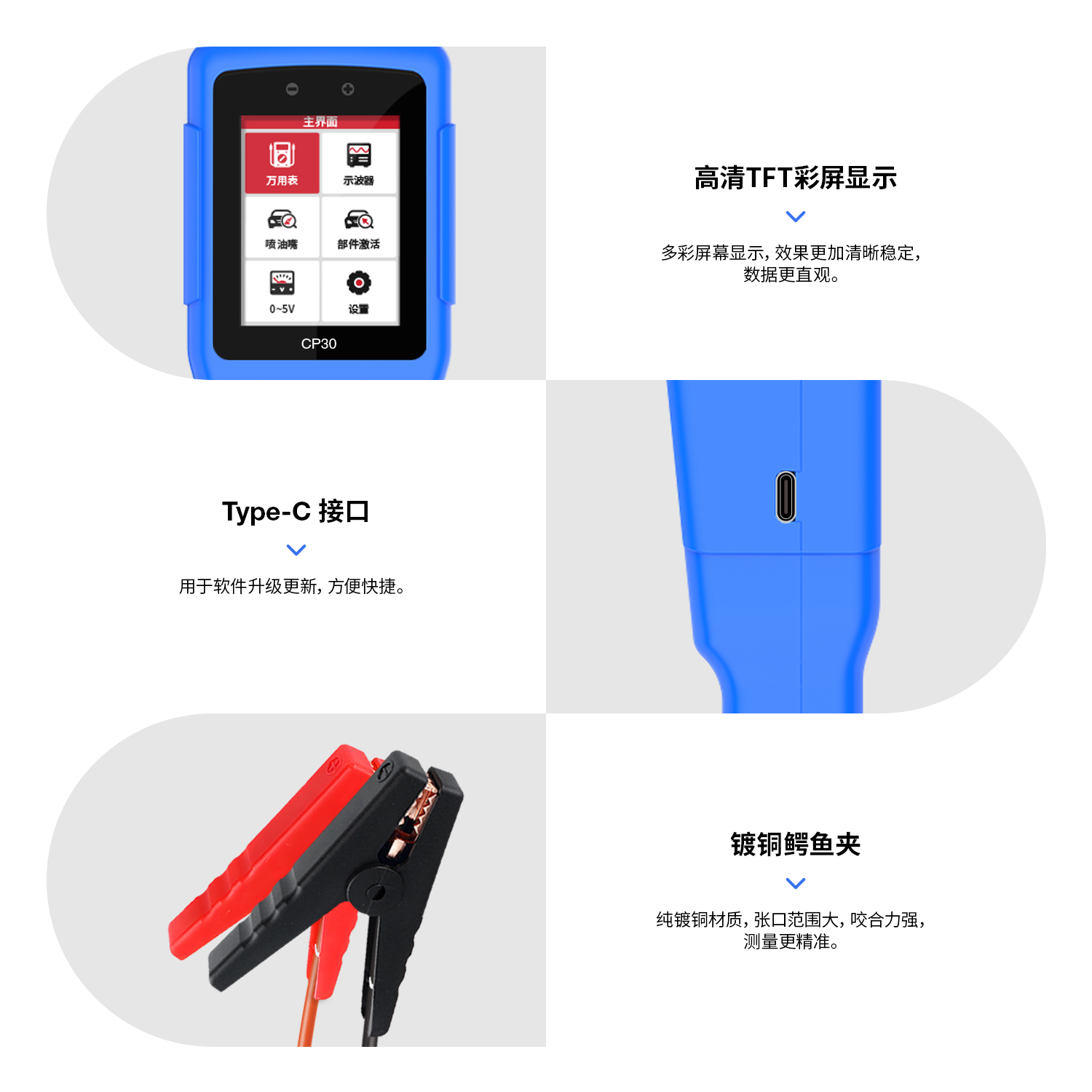
| Display | 2.4-inch TFT color display |
| Measurement/wiring functions | Voltage, polarity, continuity, ground and short-circuit assistance |
| Component activation | Positive supply or ground per instructions, permitted components only |
| Protection | Reverse-connection and overload safeguards; conditions per manual |
| Lighting and alerts | LED lighting and buzzer alerts |
| Voltage resolution | 0.1 V DC |
| Multimeter functions | Voltage, resistance, diode, continuity, polarity, frequency |
| Frequency range | 5 Hz–20 kHz (A02 manual) |
| Waveform capability | Maximum 1 MS/s sampling, 20 kHz monitoring frequency (A02) |
| CAN check | CAN_H/CAN_L voltage/polarity view, not message decoding |
| Injector pulsing | 4 presets plus custom frequency/pulse width for compatible off-vehicle injectors |
| Activation settings | 0.1–8 A current-limit setting; PULSE/MOMENT/LATCH (A02) |
| Signal simulation output | 0–5 V, 0.1 V steps, <100 mA on matching A02 version |
| Hold and rotation | Waveform hold; 180° rotation in multimeter interface |
| Software update | Type-C to computer with official matching tool/files |
| Languages | 12 including Chinese, English and Japanese; per current software |
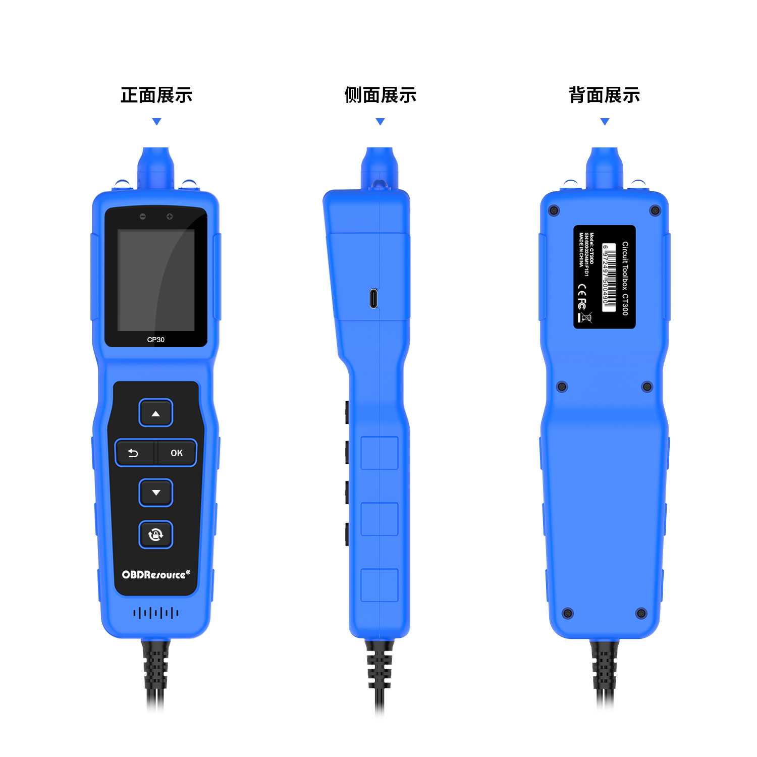
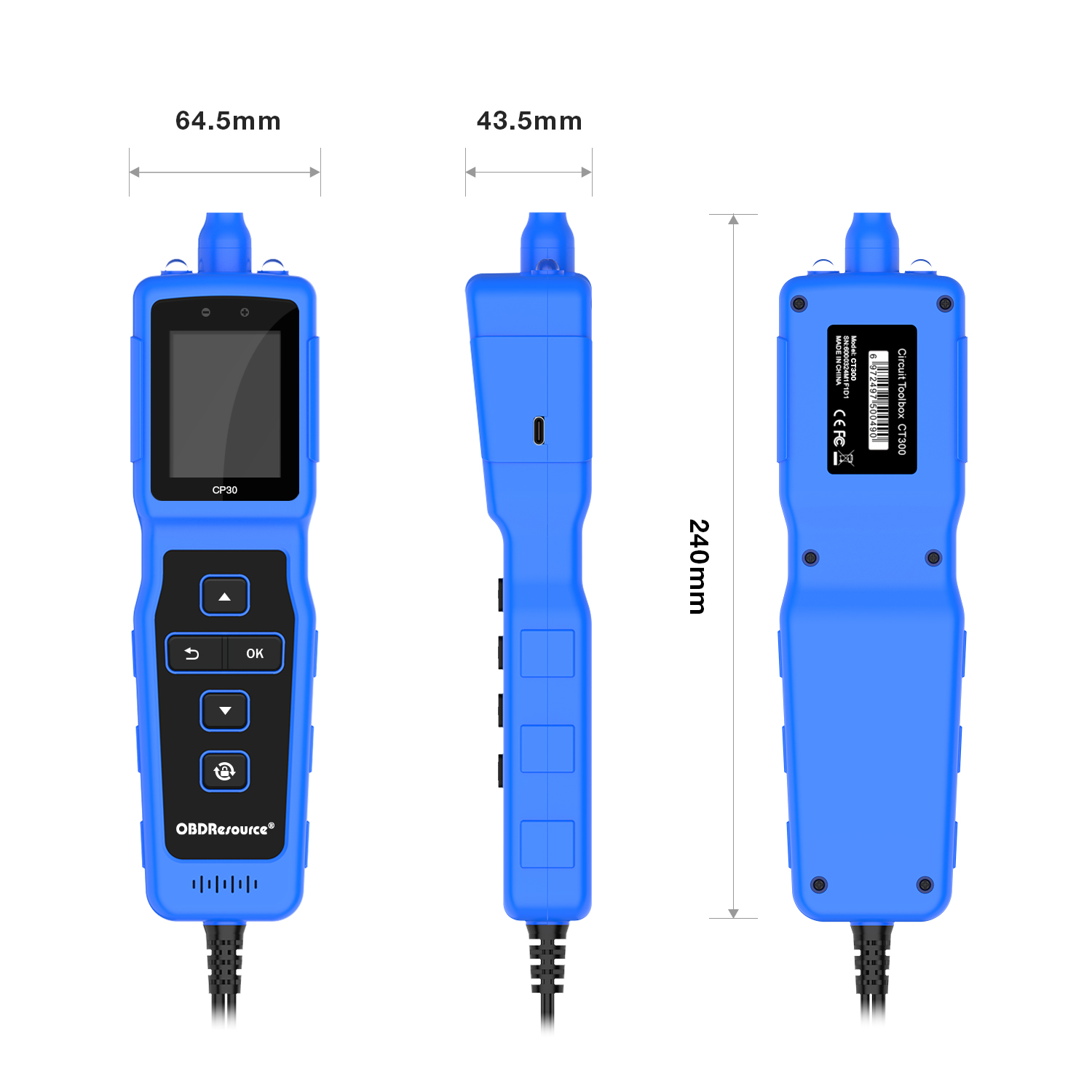
| Body dimensions | 240 × 64.5 × 43.5 mm |
| Operating temperature | −20–50°C (A02 manual) |
| Storage temperature | −40–65°C (A02 manual) |
Figures and added modes follow the CP30 A02 manual; check menus for older hardware/software. Follow unit ratings for resistance testing. Supply, measurement and activation limits differ.